📡 PCR vs Capture Arrival Drift
This rule applies to MPEG-TS streams extracted from PCAP or PCAPNG files.
The inspector compares the MPEG-TS Program Clock Reference (PCR) timeline with the packet-capture arrival timeline for the selected UDP stream. It removes the initial offset between the two clocks and then measures whether the clocks drift apart over time.
Plain MPEG-TS files do not contain packet-capture timestamps, so this rule is reported as not applicable for those sources.
What this test checks
For each PCR sample that can be matched to capture timing, the validator:
- finds the selected UDP packet whose extracted TS packet range contains the PCR packet
- reads that UDP packet's capture timestamp
- converts the PCR value to milliseconds
- uses the first matched PCR sample as the baseline for both clocks
- computes
drift = elapsed capture time - elapsed PCR time - compares the absolute drift against the configured threshold
This rule checks whether the sender's transport clock progression matches real packet arrival progression as observed in the capture.
Why drift matters
PCR and capture arrival time measure different things:
- PCR is the sender's MPEG-TS system clock reference.
- Capture arrival time is when the packet reached the capture point.
The two clocks do not need to have the same absolute start time. That initial offset is removed. What matters is whether their elapsed time grows at the same rate.
Excessive drift can indicate:
- sender pacing that does not match the PCR clock
- bursty transport delivery after buffering
- PCR generation problems
- capture timestamp quality problems
- network behavior that changes packet arrival rate over time
Pass criteria
The test passes when the absolute PCR-vs-capture drift remains at or below the configured threshold for all matched PCR samples.
Default threshold:
- failure:
100 ms
Fail criteria
The test fails when one or more matched PCR samples exceed the configured absolute drift threshold.
With the default configuration, a sample fails when abs(elapsed capture time - elapsed PCR time) is greater than 100 ms after the first matched PCR sample baseline is removed.
Chart
The chart plots PCR-vs-capture drift over capture time.
Use it to identify:
- a steady upward slope, where packet arrival time is running later than PCR
- a steady downward slope, where packet arrival time is running earlier than PCR
- sudden steps, which may indicate buffering, packet loss, or capture timestamp discontinuity
- oscillation around zero, which may indicate arrival jitter rather than long-term drift
The x-axis is capture time relative to the first selected packet. The y-axis is drift in milliseconds. Reference lines show the positive and negative configured threshold.
Passing sample result

In this passing example, the PCR-vs-capture drift stays near 0 ms and remains inside the +/-100 ms limit for the full visible range. The small movement around zero indicates normal timing variation after the initial PCR and capture-clock baseline offset has been removed.
This is the expected shape when the MPEG-TS PCR timeline and the observed packet-arrival timeline advance at roughly the same rate.
Failing sample result
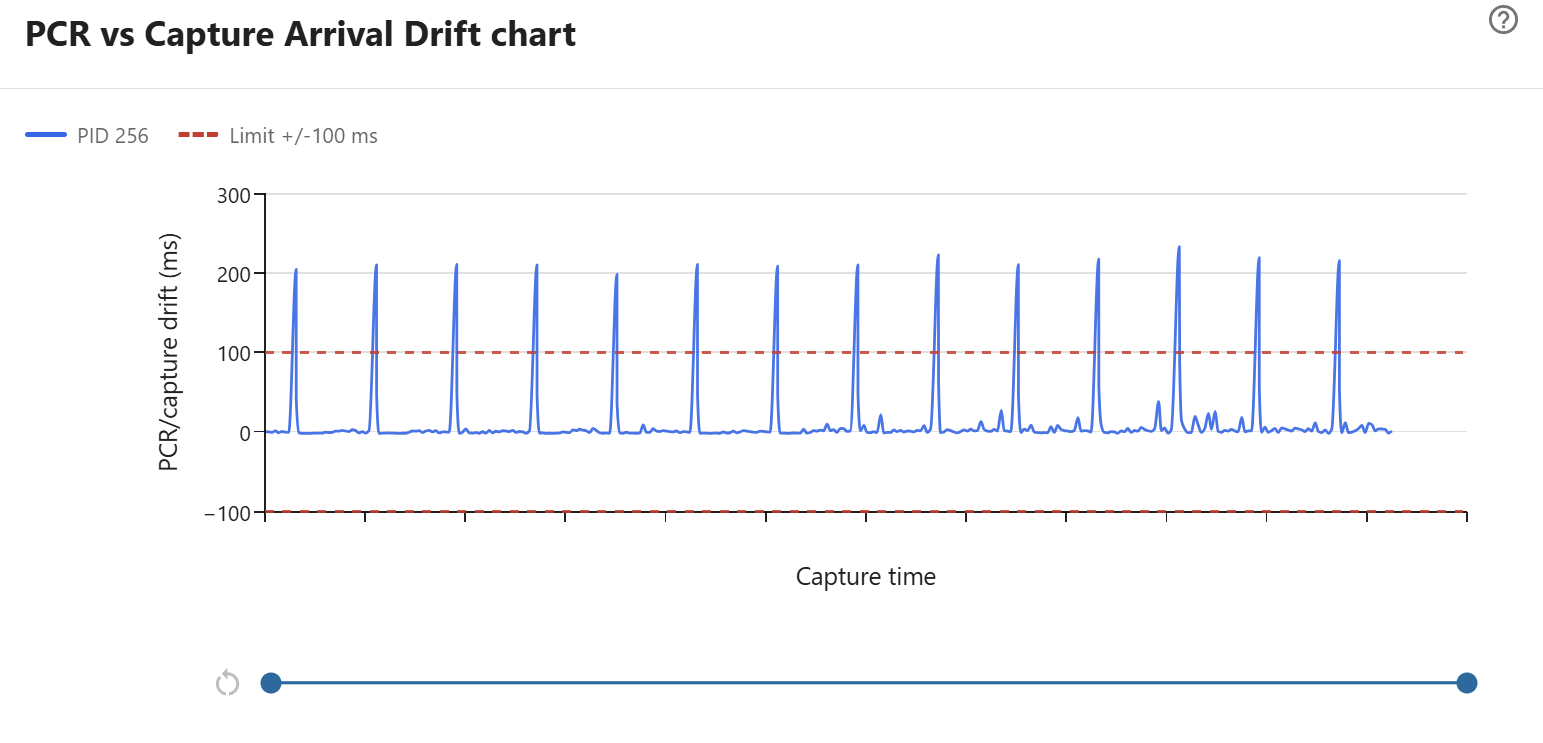
In this sample, the baseline drift for PID 256 stays close to 0 ms for most PCR samples. That means the elapsed PCR clock and elapsed capture-arrival clock usually advance at nearly the same rate after the initial baseline offset is removed.
The repeated tall positive spikes are the important result. They rise above the +100 ms limit, while the negative limit is not crossed. With the default threshold, this result fails because at least one matched PCR sample has absolute PCR-vs-capture drift greater than 100 ms.
Because the drift returns close to zero after each spike, this pattern does not look like a continuous long-term clock-rate error. It is more consistent with periodic burst delivery, buffering, capture timestamp irregularity, or PCR packets arriving noticeably later than expected at the capture point. Use the range slider to zoom into one spike and compare the same time range with Capture Inter-arrival Jitter, Capture Gap Detection, and PCR Interval results.
Relationship to other timing rules
Use this rule together with:
- Capture Inter-arrival Jitter to see short-term arrival variation
- Capture Gap Detection to find long missing-arrival gaps
- PCR Interval to check whether PCR values are inserted at a valid cadence
- PCR-PTS Drift to compare PCR with the video timeline inside the MPEG-TS stream
If PCR-vs-capture drift fails but PCR-PTS drift passes, the MPEG-TS internal timing may be coherent while network delivery or capture timing is irregular.
If both rules fail, investigate sender clock generation, remultiplexing, and stream pacing together.
How to investigate failures
When this rule fails:
- confirm the capture host clock and timestamp source are reliable
- check whether drift is gradual or appears as a sudden step
- inspect capture inter-arrival jitter near the same time range
- compare with MPEG-TS continuity-counter and PCR interval failures
- capture the same stream closer to the sender to isolate network effects
Treat this rule as a cross-layer timing check. It is strongest when compared with the other transport and capture timing charts.